

- Coordination & Specification of Drilling Routes for the Installation of Fixed Heat Sources
- Delivery and Installation of the Components
- Installation of the Thermik central control system, including field sensors
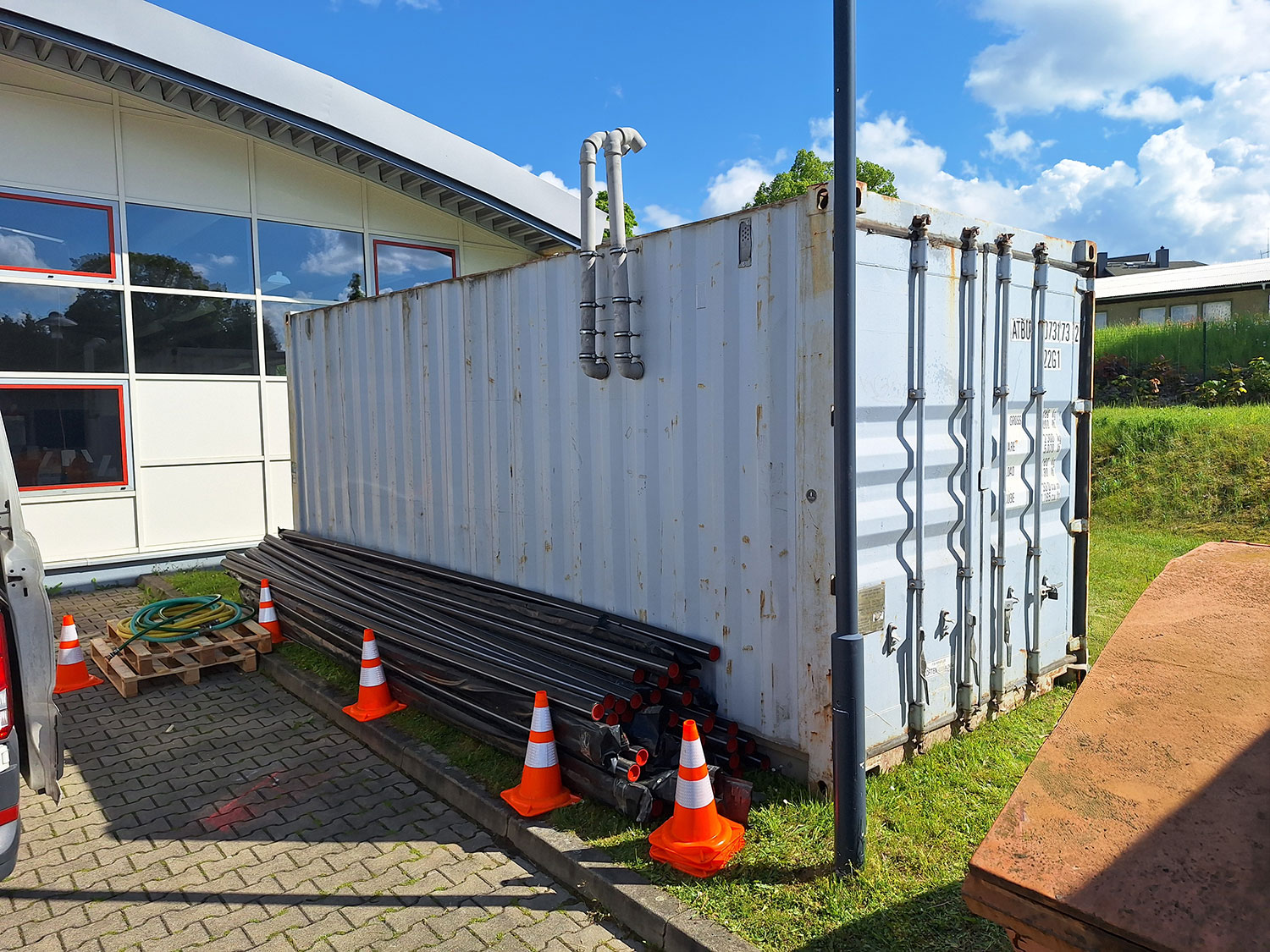
- Design and Installation of the Connected Floor Air Extraction System
- Maintenance & Operation
- Coordination of Efficiency Adjustments
An End to the Never-Ending Project: In-Situ Thermal Remediation of an LHKW Site
Some remediation projects never end—they simply drag on, year after year, without solving the actual problem. That was exactly the threat facing an actively used educational facility: A pump-and-treat system in operation since 2006 kept the LHKW contamination under control but did not eliminate it. With funding running out and contaminant levels stagnating, a change in approach was necessary—one that truly addresses the source of the problem.
Client
Education Center
Area
Approx. 100 m²
Service period
Summer 2025 through ongoing
Volume extracted and treated
180 m³
Contract value
500,000 €
Contaminants
Highly volatile halogenated hydrocarbons (LHKW), in the saturated and unsaturated soil zones, residual phase
Questions about the project
Key Services
Customer Benefits
- Efficient In-Situ Remediation of Damage Caused by an Aging Wastewater Treatment Plant
- Containing Contamination at the Source
- Sustainability considerations are addressed through a focus on actively stimulating physical processes
- Renovation can take place while operations continue
- Decommissioning of the pump-and-treat facility due to a more cost-effective mitigation measure
The Situation: 20 Years of Pump-and-Treat—and the Damage Persists
At an actively used educational site, the subsoil had been significantly contaminated by volatile halogenated hydrocarbons (VHCs) for many years. The contamination was caused by solvent leaching resulting from the site’s former use as a dry cleaner.
Since 2006, the contaminated groundwater has been continuously treated using the pump-and-treat method. However, despite long-term operation, the concentration of contaminants in the groundwater remained unchanged. The measure increasingly became a costly “perpetual solution” —a situation further exacerbated by expiring subsidies and rising operational demands.
A key challenge lay in the complex geological conditions:
The subsoil exhibited significant inhomogeneities, while at the same time there was only limited knowledge of the actual distribution of contaminants. Added to this were demanding conditions, such as the installation and operation of remediation equipment at an active educational facility, as well as logistical constraints during construction.
Additional soil tests conducted in 2018 ultimately confirmed that significant amounts of contaminants were bound in the loess loam and were acting as a permanent source of contamination for the groundwater.
The Invisible Reserve: How Loess Clay Acted as a Reservoir for Pollutants
The investigations revealed a clearly defined area of contamination covering approximately 100 m² in the subsoil. The contaminated soil zone was located at a depth of about 4 to 6 meters below ground level and had an average thickness of 1.8 meters.
The focus was particularly on chlorinated solvents:
- Tetrachloroethene (PCE)
- Trichloroethene (TCE)
The calculated mass of pollutants was:
- Approx. 111 kg of LHKW in loess loam
- Approx. 2.3 kg in a granodiorite substitute
Follow-up survey during the course of the project: The amount has now increased to more than 400 kg (discharge).
The volume of contaminated soil included:
- approx. 180 m³ in loess loam
- approx. 900 m³ of granodiorite replacement
The results made it clear that the loess loam acted as a long-term contaminant reservoir and that the groundwater remediation efforts undertaken to date had not been sufficient on their own to achieve adequate decontamination.
The Solution: In-situ Thermal Remediation for Sustainable Contaminant Removal
To eliminate the source of contamination in a targeted and permanent manner, an in-situ thermal remediation will be carried out. The goal of this measure is to nearly completely remove the potential for contamination directly at the source in order to sustainably reduce groundwater contamination.
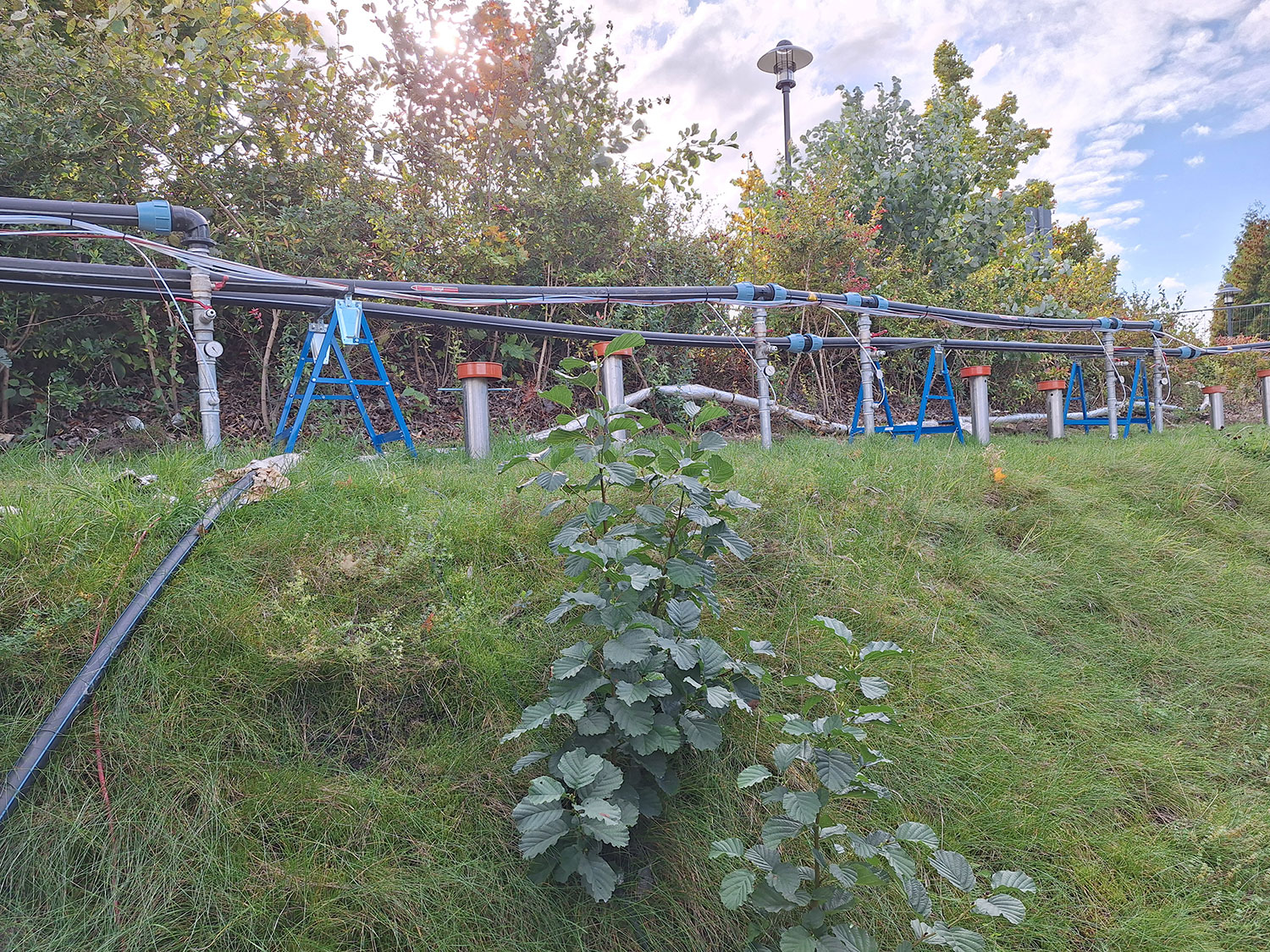
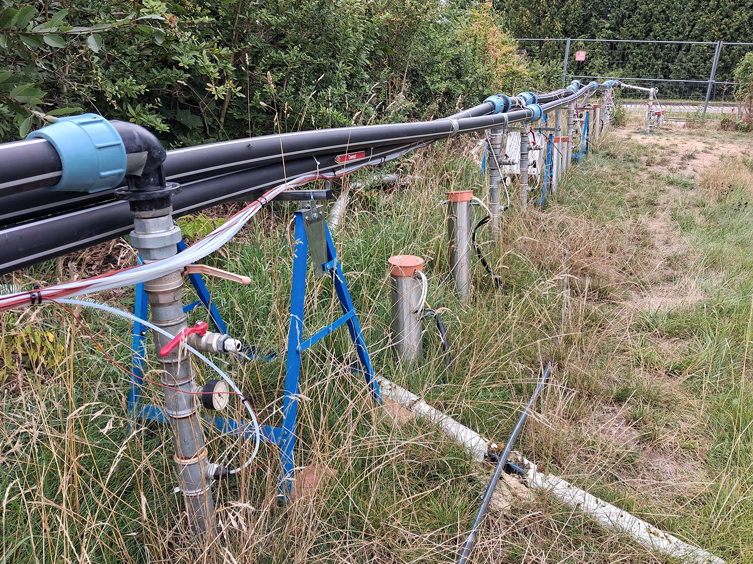
The technical concept is based on electrically powered heating lances installed along two separate remediation axes. The controlled heating of the subsoil mobilizes the bound contaminants and specifically converts them into the gas phase.
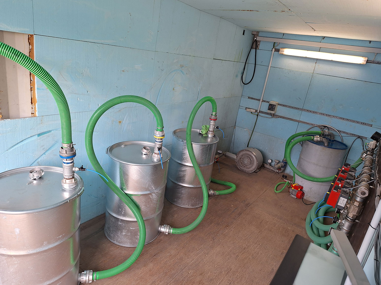
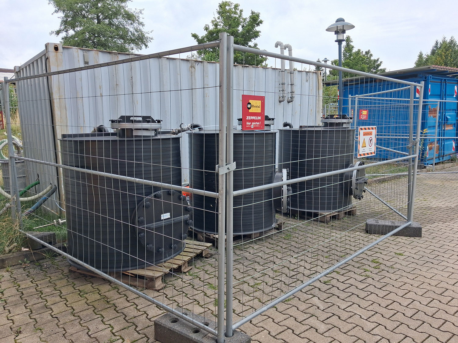
Next, all contaminants are fully captured via soil air sampling points operating at a constant negative pressure throughout the entire remediation area. The contaminated soil air is extracted, filtered, and purified.
This method enables particularly effective decontamination of sites contaminated with hydrocarbons, as pollutants can be removed directly from cohesive soil layers—where conventional pump-and-treat systems often reach their limits.
Clear goals, officially confirmed
The primary goal of the remediation is to remove as much of the contaminant load as possible from the source of the contamination and, in doing so, to minimize groundwater contamination.
Key Guidelines and Target Values:
- Reference value for indoor air: 80 mg/m³ ΣLHKW
- Sustainable reduction of the potential for contamination in the subsurface
Step by Step: Here’s How Thermal Retrofit Works
Extensive preparations were carried out before the actual renovation began:
- Plant Design
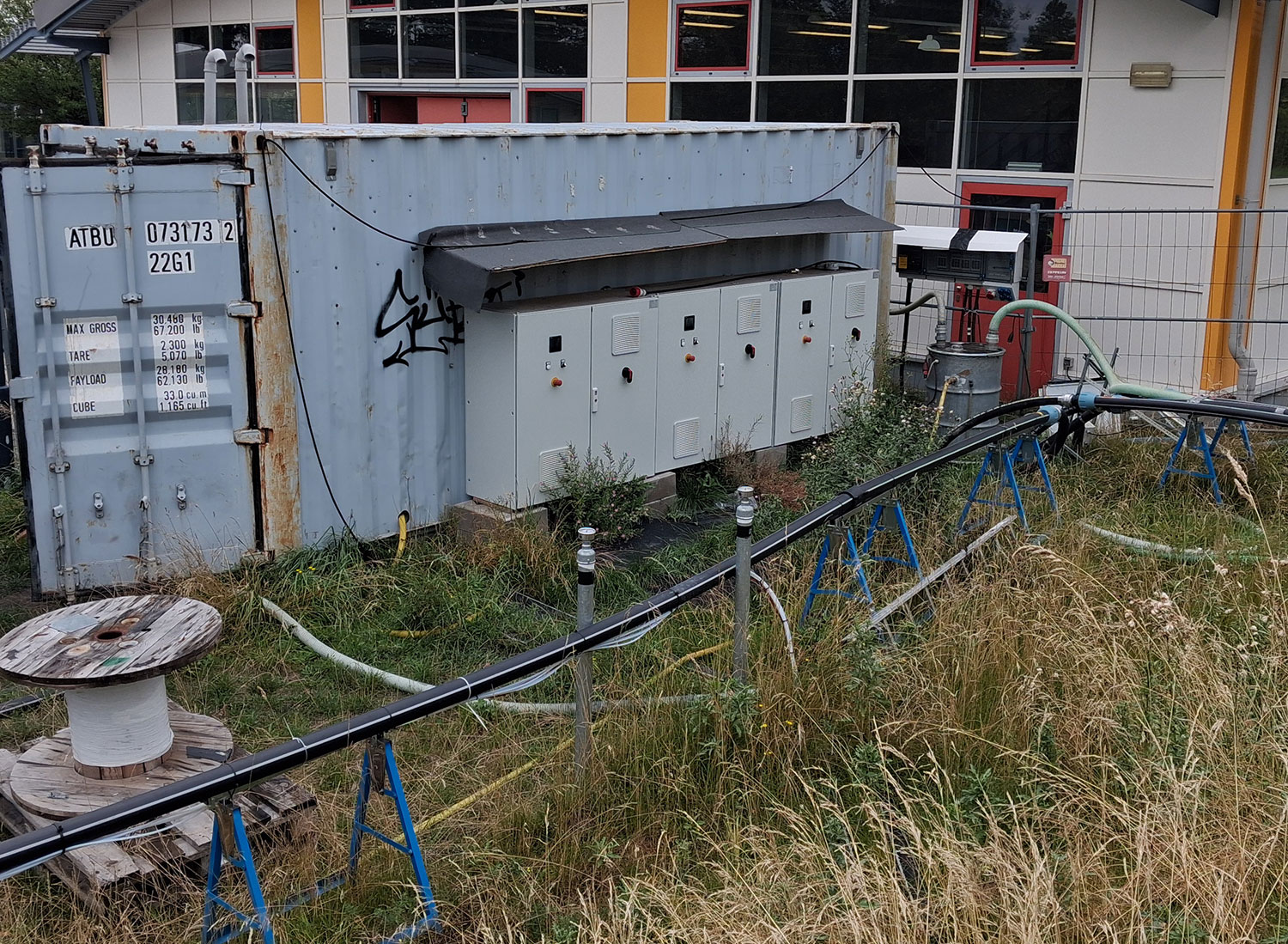
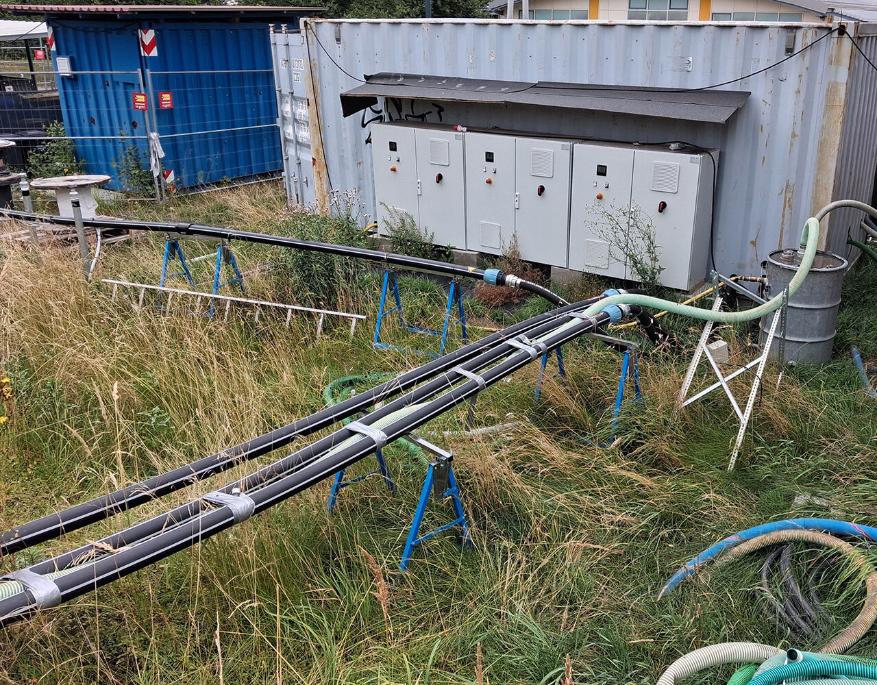
- Construction of Site Facilities
- Preservation of Evidence
- Protective and Safety Measures
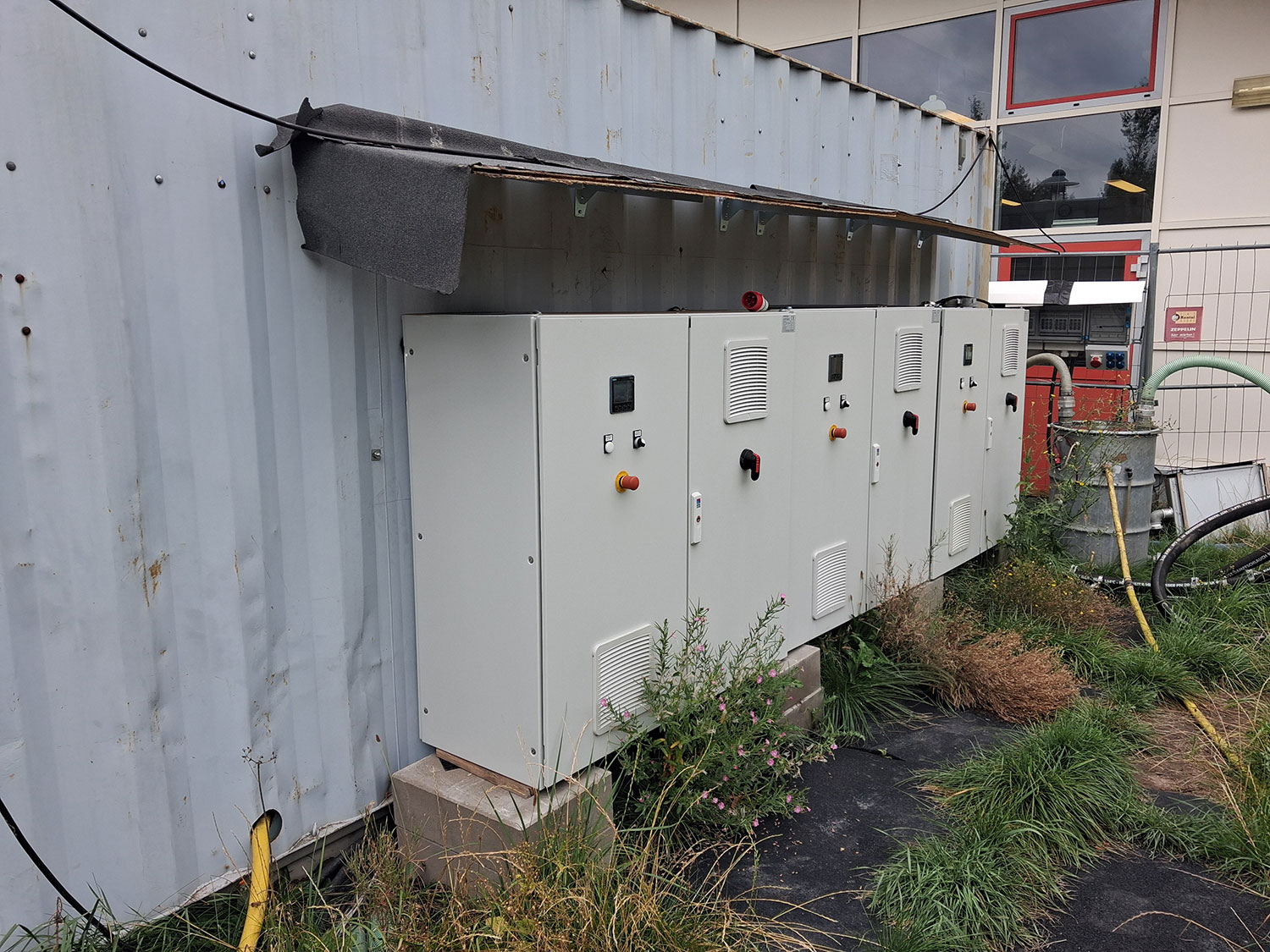
- Designing a Power Supply with Sufficient Capacity
- Supplementing Existing Drainage Systems
The technical implementation included:
- Installation of electric heating lances in 200-mm-diameter boreholes
- Heating the soil to target temperatures of up to 121 °C
- Mobilization of LHKW through thermal treatment
- Continuous floor-level air extraction for pollutant detection
- Filtering and Purification of Contaminated Soil Air
- Lowering the groundwater level to prevent the spread of contaminants
Once the complete renovation is finished, all renovation elements will be dismantled to a depth of 1 m below ground level, and the heating lances will be completely removed.
Precision Underground: The Technology Behind Heating Lances
The heating torches used were specifically designed to meet the site’s geological and contaminant-specific requirements.
Technical Specifications:
- Heating zones 4 m or 6 m in length
- Stainless Steel Casing Pipe
- Insulating Ceramic Bodies
- Electric Operation
- Heating capacity of approximately 8.3 kW or 12 kW per element
The sizing was based on:
- the spread of the source of the damage,
- the thickness of the soil layer,
- and a safety factor of 2.
This ensures uniform and controlled heating of the contaminated substrate.
Result: Significantly higher efficiency than decades of pump-and-treat remediation
The success of the in-situ thermal remediation technology is already evident during the ongoing remediation:
The actual contaminant removal rates significantly exceeded the values originally projected in the request for proposals. At the same time, this method is significantly more efficient than the groundwater remediation using the pump-and-treat technique, which has been in use for decades.
Thermal remediation thus not only significantly accelerates the removal of contaminants but also reduces the long-term costs of operation, monitoring, and post-remediation care.
The project impressively demonstrates how modern thermal restoration methods can provide sustainable solutions even for complex HVAC system damage —particularly in cases where conventional methods reach their technical and economic limits—and where it takes courage to take a different approach.